Latency is an important factor in making any human interface feel right. The Leap Motion Controller has lower latency than other similar products on the market, but exactly how low is it? The honest answer is that it depends on quite a few different variables, some of which are often overlooked.
We’ve learned from empirical evidence in building and testing motion control systems that there is some amount of latency that is tolerable by the human visual and nervous system, in that the delay is still imperceptible. This line is fuzzy and changes from person to person, but we’ve found that a good threshold is around 30 milliseconds on average.
An analogy for this threshold is the pixel density needed for a display to be of “Retina” resolution – any better, and you might not even be able to tell. You could say that being under this 30-millisecond threshold might refer to a “Nervous” controller.
Reducing latency has been a strong motivator for us here at Leap Motion since day one, and our success depends on how the latency is measured. In the first part of this article, we’ll examine various sources of delay between the time when you make a movement until that movement is fully processed and the result is visible to you. In the second part, we’ll see what happens when these factors come together, and what that means for our technology.
Hardware
Our analysis begins at the hardware level. The Leap Motion Controller features a quality mode setting which allows the amount of raw sensor data to be reduced in favor of receiving the data more frequently. For example:
- “High-Speed” Mode: Cuts the resolution of the infrared sensors to a fourth of their full resolution, but in the process almost quadruples the scanning framerate as well.
- “Precision” Mode: Allows the scanning framerate to be reduced to approximately 40% of its normal value without affecting the sensor resolution, which reduces CPU and bandwidth utilization of the device.
You can see these two modes, along with Balanced Mode, reflected below.
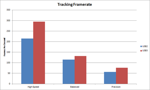
The device mode setting has a large impact on the hardware operation. In addition to changing the output resolution of the infrared sensors, the setting also affects the LED modulation and the USB controller on the device.
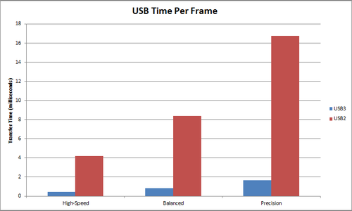
After the frame has been captured by the infrared sensors, the device’s USB controller reads the sensor data into its own local memory and performs any necessary resolution adjustments. The data is then transferred over USB from the device to the host computer. This transfer process is the biggest source of latency from the hardware level.
The exact time to perform this transfer step depends on the mode setting, whether USB2 or USB3 is used, and even the exact specifications of the USB controller in your computer. Through our testing, we’ve found that some cheaper computers have USB controllers that can barely operate at half the speed of higher-quality controllers.
Software
After the USB transfer is complete, our software on the host computer takes over. An important aspect to the Leap Motion Controller’s low cost is the fact that very minimal processing occurs on the device itself, and the processing uses some of your computer’s resources instead.
In order to make this possible, the processing must be highly optimized to do a small set of tasks based on our interaction goals, instead of taking a “brute force” approach. Here’s an overview of what occurs in the processing stage:
- After the USB transfer is complete, the raw data is conditioned to perform some basic tasks, such as compensating for background lighting and reducing noise
- The output of the two infrared sensors is analyzed to reconstruct a 3D representation of what is in view of the device
- The tracking layer searches through the 3D data to extract tracking information such as fingers and tools, and computes some supplementary data such as the palm normal vector
- These tracking results are fed into the API layer, which facilitates data transfer with any connected client applications
At this point, we could stop our analysis, now that the tracking data is fully computed and available for use in your client application. However, the bulk of the contribution to perceived latency is yet to come.
Display
The job of the display system in a computer is to take a high-level scene description and some bitmap graphics, and show them on your physical monitor. There are many components in this system, including:
- the foreground application
- your operating system
- graphics drivers
- graphics card
- the circuitry in the physical display
In order to make this complicated system work properly, there are many temporary storage buffers that act as intermediaries between one processing stage and the next. The time it takes to copy, process, and read these buffers quickly adds up.
The primary contributors to display system lag are vertical synchronization (VSync) and the circuitry in your monitor. VSync is a method to prevent screen “tearing,” caused by simultaneously displaying the contents of two images of data that were created at different times. VSync ensures that only the data from a single point in time is displayed on your monitor. In order to provide this guarantee, it must delay the steps earlier in the process, until the graphics drivers are ready to send the next image to the display.
Needless to say, this intentional delay adds quite a bit of latency. The penalty can be somewhat mitigated through the use of Triple Buffering, a technique that allows rendering to two off-screen buffers at unlimited speed while guaranteeing that the “swap” between the current off-screen buffer and the on-screen buffer will only occur when the graphics drivers are ready.
Display panel input lag is the other major contributor to perceived latency in the display system. It is very rare to find a display that simultaneously has low lag, high viewing angles, good color accuracy, high resolution, and a small physical footprint. Generally, “gaming” monitors will sacrifice color accuracy in favor of speed, while professional imaging monitors will do the opposite.
First, the display must convert the raw video output signal (such as DVI, HDMI, or DisplayPort) from the graphics card into a format that can be understood by the display hardware. Then, the raw image data is processed to scale the output to the proper resolution, perform brightness/contrast/color adjustments, and optionally perform some additional tasks like edge sharpening or motion interpolation.
Finally, there is the response time of the actual pixels inside the display. For example, in a liquid crystal display (LCD), small sets of crystals for each color channel (red, green, and blue) adjust their polarization to allow different amounts of the white backlight to pass through. These crystals can’t move instantaneously, so the time it takes (usually measured in a grey-to-grey or white-to-black transition) is the response time of the display panel.
Now that we’ve seen all the various latency factors that come into play, it’s time to see how they all come together in part two.
UPDATE: June 2014. We’ve been continually refining and optimizing our tracking over the year since this post was published. Latency will always be a challenge, so long as the speed of light and laws of thermodynamics still apply, but these are issues that we’re excited to work on – “not because they are easy, but because they are hard.” The current software currently only uses USB 2.0 data speeds, but in the future will also take advantage of USB 3.0 speeds.
[…] Kinect, using tightly spaced beams of infrared to see what’s in front of it. Combined with ultra-low latency and you’ve got a very sensitive, very responsive input system. As the demos show, you can […]
February 13, 2014 at 9:12 am[…] We looked at how to take a real-time 3d scanner and sync that up to a virtual environment that a person can physically interact with in a visceral way. To make this work we had to figure out how to scan someone’s position in real-time, export that to a particle engine, emit particles at that point in time, and render that to the display frame. We also know that the latency needs to be less than 30 ms to effectively trick the brain into thinking what it is seeing is real-time. There is a great blog post by the developers of leap motion on this subject. [2. https://www.leapmotion.com/blog/understanding-latency-part-1/] [3. https://www.leapmotion.com/blog/understanding-latency-part-2/] […]
April 19, 2014 at 12:45 pm[…] Leap Motion Team latency, software Previous PostUnderstanding Latency: Part 1 Next PostInside Leap Motion: Meet Our Hardware […]
June 17, 2014 at 7:20 am[…] While this “human perception threshold” varies from person to person, we’ve found that 30 milliseconds is a good target […]
July 20, 2014 at 8:04 am